Farnell L30 Stabilised Voltage Supply [1963 Germanium]
-r.jpg) Farnell Instruments made several series of power supply, including fixed-voltage modular and OEM types, 'Bench' (or sub-bench) variable output types, 'Laboratory' variable output types, the cheaper 'Educational' variable output types, the triple-output TOPS series, the larger TSV series, and high-power rack mounted variable output 'H' types.
Farnell Instruments made several series of power supply, including fixed-voltage modular and OEM types, 'Bench' (or sub-bench) variable output types, 'Laboratory' variable output types, the cheaper 'Educational' variable output types, the triple-output TOPS series, the larger TSV series, and high-power rack mounted variable output 'H' types.
Images and notes on 45spaces.com:
L30 Stabilised Voltage Supply
L30/T
L30/2
L50
TSV 30/5 CL
TSV30/5 EC
TSV30/2 EC
TSV 30T/2CL
There was also an 'E' Series equivalent, "Stabilsed Voltage Supply Type E30" which is identical except for presentation details.
Not to be confused with the later all-silicon E30/1B
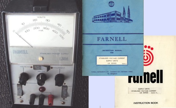
From about 1969 these were superceded by the all-silicon "L30 Series", described in the accompanying manuals as Stabilised Voltage Current Supply Units but shown on the instruments as "Stabilised Power Supply". The series consists of five 'single units' types L30A (0-50V 0.5A), L30B (0-30V 1A), L30C (0-10V 3A), L30D (0-30V 2A), L30E (0-30V 5A), L30F (0-12V 10A), and three 'twin units' types L30AT, L30BT and L30DT. Selection of constant-voltage or constant-current operation was made with a link on the base of the unit, and these units had toggle- or rocker-switches and a single full-range voltage control.
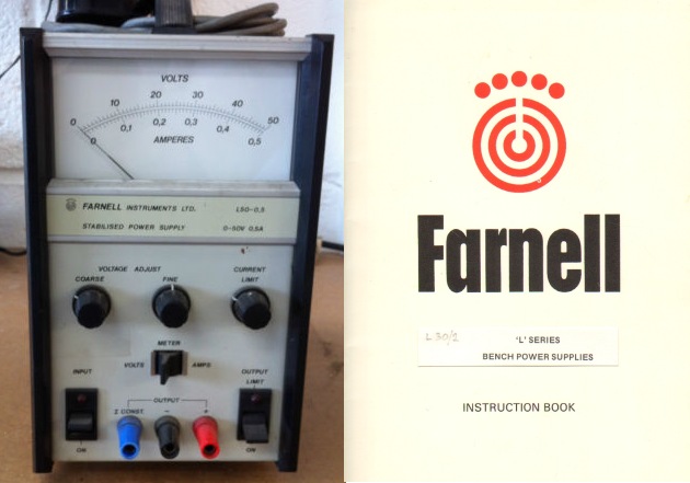
Then from about 1978 there came the "L Series" consisting of 9 units including "L30" single types L30/1, L30/2, L30/5 and twin types LT30/1 and LT30/2, the type numbers now denoting the voltage and current ratings. These had lever switches and a single full-range voltage control.
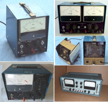
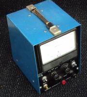
FARNELL L30 STABILSED VOLTAGE SUPPLY
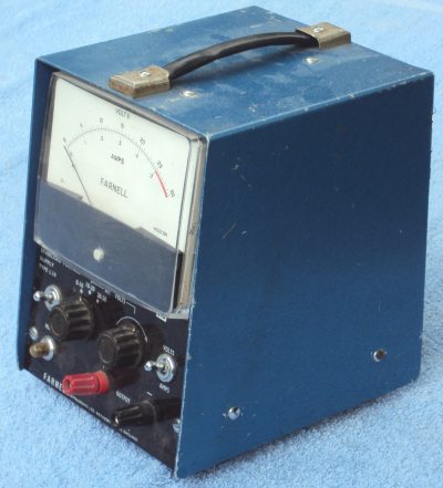
The L30 Stabilsed Voltage Supply can be recognised by the sloping front of the case, finished in blue Hammerite paint, and the full-width meter which takes up half the front panel. The current limit control is on the rear panel.
The L30 may have been the first production model laboratory bench supply from Farnell and appears to be based on an earlier DC supply unit, the PSO 30/2, described as being "constructed for use as a sub-unit in other equipment. Hank bushes are incorporated to allow fixing to panels or chassis". I do not know if these were open-frame or enclosed units. They were introduced in 1961 and the schematic and specification are the same as the L30 but without the metering and current limit, using three OC36 in a Darlington configuration.
Many examples of these L30s can be found still working, but it would be inadvisible to seek out these Germanium-circuit models for regular use unless you have an affection for vintage solid-state equipment and are prepared to undertake occasional repairs and refurbishment; otherwise one of the later Laboratory series would be a sensible choice.
A common abuse of these power supplies is battery-charging, which is likely to result in tears. Other battery-charging devices are available if you do not wish to destroy the power transistors, or at least add a series diode between the PSU and battery for reverse voltage protection!
SCHEMATIC DIAGRAM
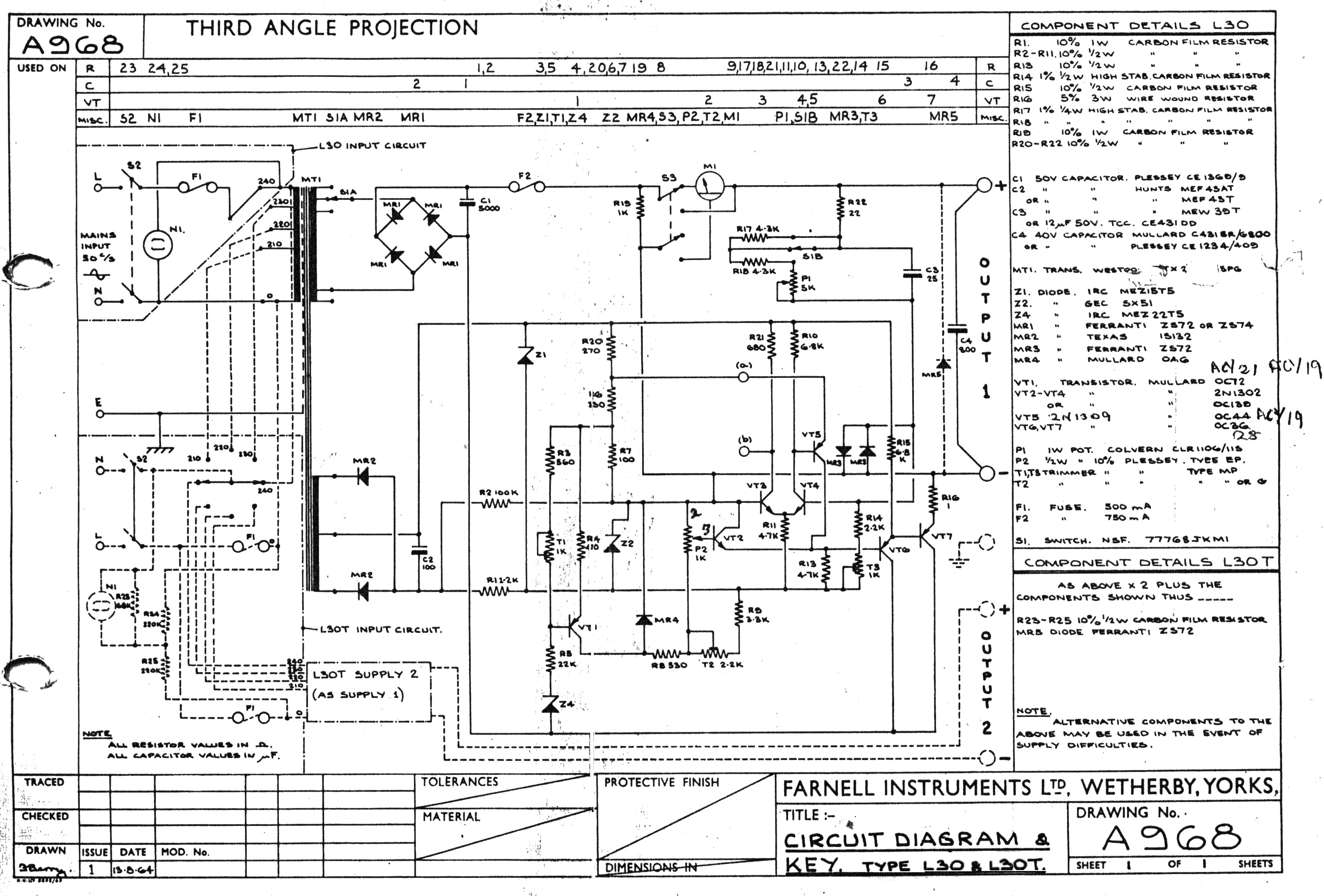
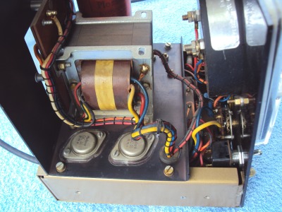
A pair of OC36 power devices is used for a Darlington-pair common collector output, maintained by the control circuit on a single-sided PCB, operating from a 20V power line regulated by Z1. Z2 provides the 5.4V reference voltage for long-tail pair VT3+4. VT1+2 provide the current limiting
Replacement of the output devices and voltage comparator by modern silicon devices is of course a possibility.
The devices used were changed during the production period: VT1 was OC72 or ACY19 or 21, VT2-4 were OC139 or 2N1302, VT5 was 2N1309 or OC44 or ACY19, VT6-7 were OC36 or 28.
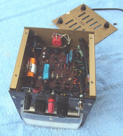
Later PCBs had a revised layout and were silk-screen printed with the component designations.
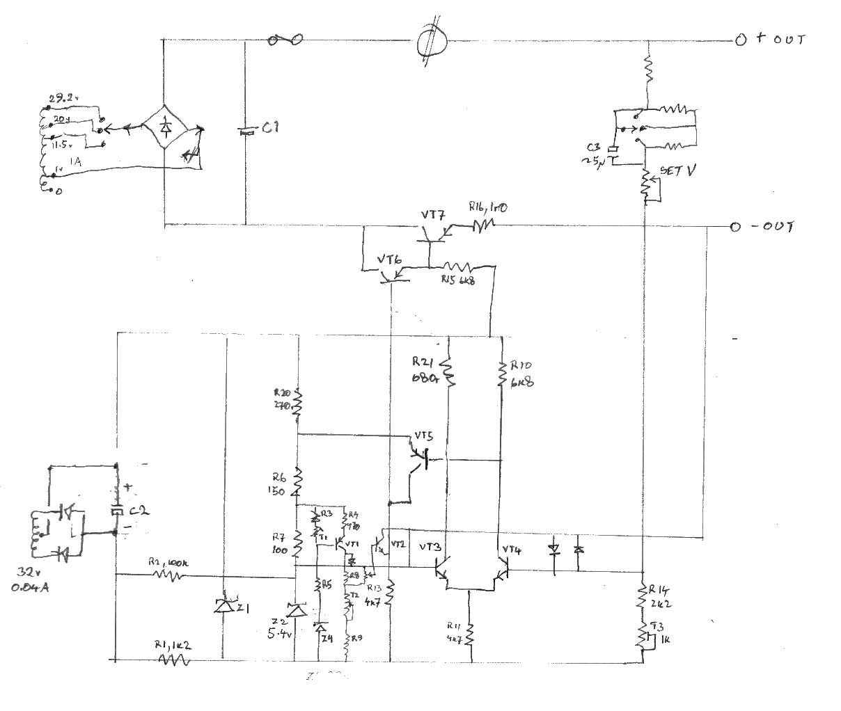
Schematics of garmanium-device circuits from this era can be challenging to follow, the lack of any common voltage reference makes them appear to have been drawn by a madman; I found it necessary to draw a simplified schematic in a manner which may be more familiar to engineers who grew up with planar silicon devices.
The only original service information I include here is the circuit schematic, but the full Instruction Book can be seen on UK Vintage Radio Forum
Early and Late PCBs:
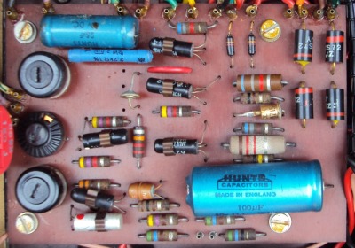
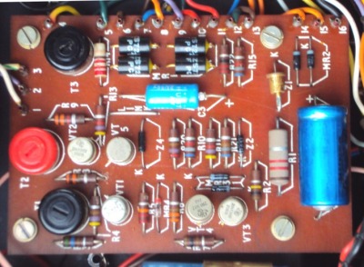
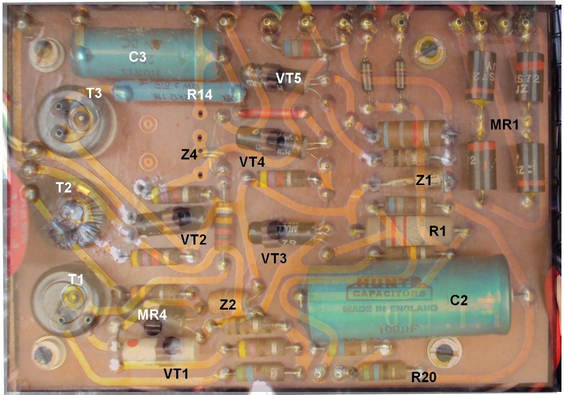
View the track-side of the PCB superimposed on the component layout, with added notation:
J.Hardstone Aug.2015, revised Aug.2017