The Sony XDR-F1HD AM-FM 'HD' Tuner can be used on Global Tuners as an internet-controlled receiver for FM-Dx. The motivation for using the XDR despite its having no compuer interface is the XDR's superb performance for weak-signal FM reception
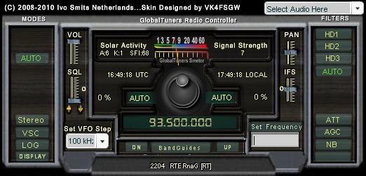
The control system deveoped by Olivier Guillaume for GT uses the unit's IR remote-control sensor to control the frequency. The 'remote' is emulated in a Seeduino board (Arduino clone board) driving an IR LED
Here is a description of this board:
"Arduino is an open-source electronics prototyping platform based on flexible, easy-to-use hardware and software. It's intended for artists, designers, hobbyists, and anyone interested in creating interactive objects or environments"
(See Wkipedia for more)
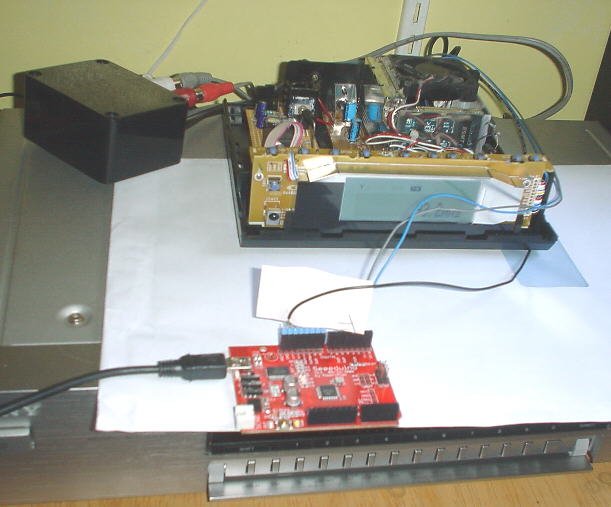
For GT, the audio line outputs are connected to the online computer soundcard for the audio streaming. The Seeeduino has previously been programmed with the 'firmware' or Arduino 'sketch' and remains connected to the online computer to control the XDR. If the XDR is modified to output the I²C bus the Seeeduino will also decode the RDS and S-meter data for display on the GT 'modern' interface *
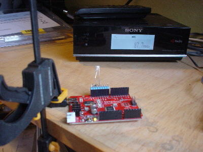
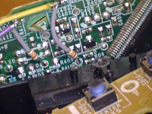
This shows the Seeeduino connected to the XDR micro bus (the IR-LED is covered by thin paper to improve control while the case is removed) -
I have experienced problems with reliable IR control. The side-facing LED shown here seems to be too 'bright' for the XDR IR receiver, and easily overloads it if placed too close. The Seeeduino is capapble of driving LED's at saturation of the output drivers, without damage to either the LEDs or the ATmega8 chip. This gives an LED current of ~ 70mA (at 5V) which I have reduced to ~ 3mA (at 3.3V) with a series 820r resistor.* Maybe it could be reduced further. I have tried a piece of paper as a diffuser over the LED, which improves reliability. The LED is driven from Digital pin 13, cathode to GND
* NOTE - if the Seeeduino is to be connected to the XDR's data bus, ensure the Seeeduino is switched for 3V3 operation
The XDR '_SDA' line goes to digital line 2, '_SCL' to digital line 3, and GND to GND. I have added series resistors, 1k is suitable, in the hope this will provide protection to the XDR micro should anything cause the Seeeduino to write to these lines.
Further details of the GT system requirements, audio streaming, port settings etc. can be found on the GT pages, and GT Admin are always happy to help new site-operators
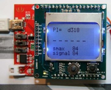
Cédric Lamouche has developed a Seeeduino board RDS decoder for stand-alone use with the XDR-F100HD & XDR-S3HD. This displays the PI code and an accurate S-meter. It can also interface with a PC to show the data and to create reception logs.
See Cédric's blog or download the first review of the kit, from Günter Lorenz
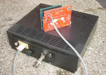
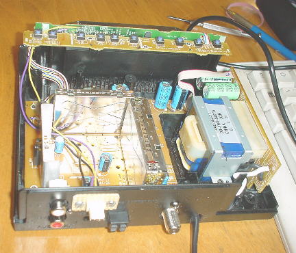
I take the supply for the display board from the tuner; about 70mA is required at any voltage in the range 7 - 20V. There is a 10.5V supply available in the XDR-F1HD (or ~12V with my modifications) and the display board has its own voltage regulator. The display supply can then be switched off in 'standby' with a high-side switch, for example using two transistors
The required connections to the XDR data + clock lines are the same as for the control board described above
Return to the XDR-F1HD main page
J.Hardstone - Last updated 24 November 2009