for use on the former Soviet Bloc FM broadcasting band
The band 65.84 - 74.00MHz was chosen by the USSR and many of its satellite states for FM broadcasting on the VHF Band, or YKB (from the German 'Ultrakurzwelle')
Before the dissolution of the USSR, the band was used also in Czeckoslovakia, Hungary, Poland, Bulgaria, Roumania and briefly in Albania. In eastern Asia, the OIRT band was used for a short period at the start of FM broadcasting in the 1960s, running in parallel with the CCIR band in (mainland) China, Mongolia, Thailand and N.Vietnam
Although its use was discontinued in many of the states following Perestroika, the band seems to be having something of a revival with the growth of commercial broadcasting. Hungary has discontinued since 2006 and Armenia, Azerbaijan, Kazakhstan are no longer active. Countries which still use the OIRT band at the time of writing are Belarus, Moldova, Russia (including Kaliningrad), Turkmenistan & Ukraine, and 'Sporadic E' propagation can give periods of good OIRT reception in the UK and across Europe from the more westerly of these regions¹. For the long-distance listener (dx-er) it is a treat to listen on a band 8MHz wide which normally is completely empty, but which is capable of providing periods of clear reception during the 'Sporadic E' season from several distant countries. Usually only one or two transmitters will occupy the band for a few tens of minutes, but when the ionisation is widespread and intense the band can become jam-packed with pop stations, speech, news and cultural programmes for many hours
It is interesting to note that, although the modulation details are the same as in the western CCIR FM band, occupying the same 200 - 250kHz of spectrum, the channel spacing is now 30kHz, rather than the original 100kHz. This is comparable to the 'offsets' as used in TV channels to avoid co-channel interference. The pre-empahsis is 50kHz as in western Europe, and Zenith multiplex stereo is increasingly used, as well as the Soviet system in which the difference signal is transmitted as an AM reduced-subcarrier signal at 31.25kHz.
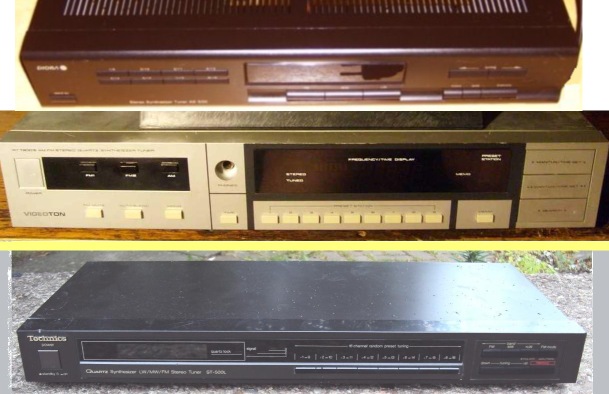
Tuners made for the band occasionally turn up on ebay.de, and there must be heaps of abandoned tuners in, say, Poland and Hungary. Locally produced PLL models were made by Diora in Poland and Teleton in Hungary. Several PLL synthesised models have been produced by Japanese manufacturers including Sony and Technics and generally offer manual switching between the two stereo systems. However, the 'DX' community tends to use high-end 'scanning' receivers or general-coverage VHF receivers, such as the Icom PCR-1000 or R7100 for this band. Alternatively, a dedicated receiver for the band can be made cheaply by modifying an old Band II FM tuner. The ideal model to choose would have both an FM 'Tuning Meter' and Signal Level Meter, but the choice of tuner requires internal inspection of candidate tuners to ascertain whether the mechanical construction will allow access to the necessary front-end tuned circuits.
DESCRIPTION
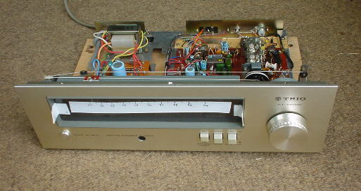
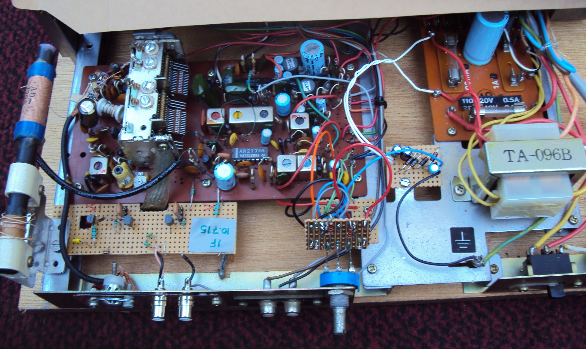
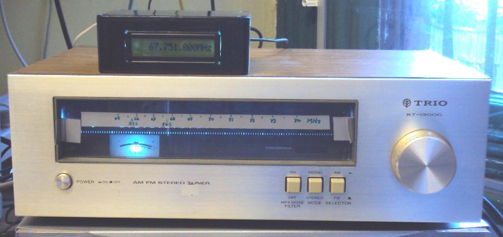
Here I have modified a typical mechanically-tuned tuner from the 1970's (with Tuning Meter) in such a way as to give the required frequency coverage with very low levels of spurious response to signals in the CCIR 97.5 - 108MHz FM band. In order to display the 30kHz channel accurately in a receiver having a bandwidth greater than 30kHz, the sensitivity of the analogue 'tuning meter' was increased, and a buffered LO output was made available for use with an external frequency counter.
Before starting to modify an old tuner, you should be confident of its performance in Band II. I strongly recommend that you measure the 'quieting' performance of the tuner, to ensure that the sensitivity is suitable for 'Dx' work, and for confirmation of the sensitivity after the modifications. There are several articles on receiver sensitivity and noise measurements on the Repeater-Builder website - see for example 20 dB quieting and what it means
. This requires a signal generator with calibrated output level. See my results of quieting measurements on some typical tuners.
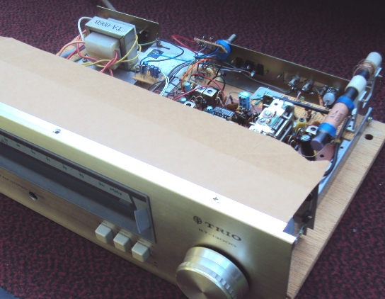
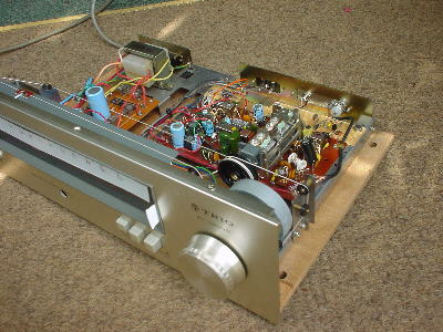
The tuner originally had two IFT's and two ceramic filters, plus the usual discriminator transformer, and the IF bandwidth was too wide for DXing. Even in the wide, empty spaces of the OIRT band, the discriminator 'S'-curve resulted in strong stations appearing three times on adjacent channels. Adding another two narrower (110kHz) cerafils separated by a gain stage, cleaned up the response to 'DX' standards.
A single-conversion receiver topology will inevitably suffer spurious responses from the very strong local Band II FM broadcast signals, experienced throughout the world. The first approach to avoiding these spurs is to run the LO below the signal frequency, so that the image response lies in the range 44 - 53MHz, where strong signals are unlikely. However, the 2nd harmonic of the LO then gives spurs within Band II. These were made insignificant by adding an 80MHz LPF in the aerial input
Although the mechanical tuning dial can be read to within 100kHz, this is not accurate enough to display the 30kHz channels. Ideally it should be possible to read the frequency within 10kHz as there still some of the old 100kHz channels in use
Amplifying the tuning-meter signal gives a full-scale display of about ±40kHz on the meter, allowing tuning to within 5kHz of centre frequency. Coupled with an external frequency counter, this is ample resolution to identify the 30kHz channel being received, once the discriminator tuning has been accurately set to the IF centre frequency (measured in this instance as 10.715MHz). Ideally the counter should have a resolution of about 1kHz and a refresh cycle of 100ms or less
Unfortunately, the discriminator coil tuning in the tuner chosen here is susceptible to temperature changes and also shows a 'creep' with time due to the use of a rubber band to secure the core, so it was necessary to add a 'null' control for the tuning meter, which is set with reference to a calibration signal
FREQUENCY DISPLAY
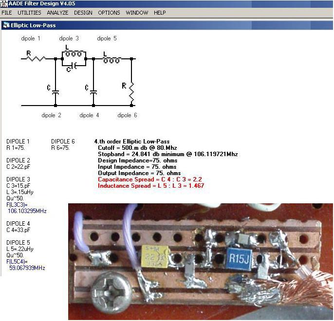
A frequency counter with programmable IF offset was needed, so the DFD4 from AADE was chosen to give an accurate frequency display. The DFD4 can be programmed for + or - offsets in 1kHz steps, so was ideal for this application. This counter does not have any gain before the prescaler, and additional gain was needed, using a simple common-base amplifier. The 5V supply for this was taken from the display regulator
To complete the calibration line-up, a calibration signal is needed to allow accurate calibration of the meter balance control. Although the 70MHz frequency-standard beacon GB3BUX is well-received here, its amplitude keying causes a false balance reading. A 6.000MHz crystal can be used in a calibration oscillator, and mounted in the receiver or display box, with a press-switch to turn it on. The frequency should be calibrated, say against the Radio Moscow evening transmission on 12.000MHz. With an untuned collector this oscillator can give sufficient output with a few cm of wire as an antenna if mounted within the tuner, but for more output at 66 + 72MHz a tuned circuit can be added as shown
Crystal calibration oscillator
DRAWINGS
Hand-drawn schematic of original circuit & mod's
For the re-tuning of the front-end, suitable coils could be wound on any suitable formers. In particular, the oscillator coil should have a ferrite core to allow fine adjustment of the frequency range. The popular Toko S18 series is ideal here.
Two extra cerafil's added, with a longtail-pair gain stage, between the original IFT & IF gain stage.
an integrating opamp for the tuning meter, to increase sensitivity but avoid overloading with noise
LO Buffer amp - a compromise between simplicity and gain /isolation for a 50ohm output of -15dBm to an external frequency counter.
4th order Elliptic LPF added at aerial input to reduce responses in Band II
preamp for counter
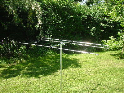
AN OIRT ANTENNA
A suitable 2-element Yagi with folded dipole can be made from commercial antenna parts. The dipole shown here was made by grafting the 'folds' from a Band II antenna onto some new elements, and the reflector used 2 more elements supported by a dipole insulator with a shorting wire across the terminals. A 4:1 balun was made using a ferrite bead. More details on this page
Any mechanically-tuned FM tuner could be considered for modification if the RF circuit is accessible for modification, but a good quality unit will give better 'dx' performance. The deficiencies of the unit used above were the minimal IF filtering, a demodulator which is not sufficiently stable and symmetrical for critical tuning, and the lack of a signal strength meter
No doubt a PLL-synthesised Band II tuner could be modified, with suitable programming of a PIC, to give a fully synthesised OIRT tuner. The divider ratios, or the reference frequency, would have to be changed for the 30kHz channels. Note that the 30kHz channels are not at integer multiples of 30kHz, but the resulting LO frequencies are, for low-side mixing with an IF of 10.7MHz. This would be a nice project for someone with programming experience!
¹There is a list of current OIRT Transmitters in the FMLIST pages, and Jürgen Bartels maintains a log of the stations he has received in Niedersachsen
These lists need some maps to see where the propagation lies; one useful map is
Wikipedia - Russian Regions
 (from the German 'Ultrakurzwelle')


