SOME NOTES about the Telequipment D61 & D61A oscilloscopes
which may be of help to anyone working on these models
DESCRIPTION
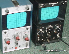
The Telequipment D61 and D61A oscilloscopes are fairly basic 10MHz oscilloscopes, dating from the 1970's and suitable for servicing and general laboratory use.
While these models are often available quite cheaply, they promise to be very reliable and indefinitely repairable due in particular to the use of a mains transformer to generate all supply voltages, including the EHT lines, rather than using the now ubiquitous inverter. Most components and assemblies are easily accessible for servicing, and replacement components should be possible to find for the forseeable future, meaning that the maintainable lifetime should be limited only by the CRT.
The D61A is a slightly later version, retaining the same circuit board, but with revisions to the channel input amplifiers and trigger circuits carried on sub-assembly boards. The only other changes from the D61 are the use of PCB sub-assemblies to carry attenuator components, and a revised case with elaborate bezels and a fixed cover which makes access to some components difficult.
The cal procedure for the trigger circuit has been revised in the D61A and now makes sense. Use the trig cct procedure in the D61A manual when calibrating either instrument.
When these 'scopes come up for sale, they may be struggling somewhat to convince of their competence as serious test equipment. They may show hum on the traces, poor triggering and a sweep rate which is influenced by the Y-channel input signal. The three essential procedures to be impemented are then:
1) Obtain the relevant Service Manual - see the notes below.
2) Replace all electrolytics in the PSU section, preferably with brand-new components, if there are any signs of hum. You may wish also to consider replacing all electrolytics on the board, prophylactically, at a later time when you have decided you value the instrument sufficiently to want to keep it working into the distant future.
3) Carry out the full calibration procedure as detailed in the Manual. The first adjustment is to set the -7.5V supply, and doing so will immediately necessitate the completion of all other adjustments. If suitable standards of voltage and frequency are not immediately available, the settings for amplitude and time calibration and pulse response can be left until later. However, the internal calibrator can be set accurately using a DVM on the DC Volts range, which should be set for a reading of -0.25V, and then can be used for setting the vertical gain.
When newly calibrated, the unit will show a crisp clear trace with negligible hum, and bomb-proof triggering from LF to HF. You will be keen to clean the instrument thoroughly, but do resist the temptation to rub vigourously at the screen cursor or the scale markings. Better to leave the markings unattenuated than to have them spotless but rubbed away!
ADDITIONAL DRAWINGS for these INSTRUMENTS
The full service manuals are available elsewhere in pdf format. Both are to be found on the 'web, for example on Jonz Old Test Equipment pages, to which I am much indebted. However, such scanned documents do not preserve the original A3 page layout of the printed schematics. I have stitched together the A3 schematics for printing out on A3, which makes for better schematics to use 'on the bench'. Also, the layout diagram for the main board, while originally very useful, benefits from the addition of some colouring of the test points and connecion points, as well as stitching. The D61A PC226 also benefits from colouring the connections.